

Our Automatic Microgreens Stand needs a lot of electronic parts, among them a Soil Moisture Sensor. When growing anything; soil, water, light and controlling their quantity becomes very important for good results.
There is a lot of information and sensor products available on Internet. Majority of them are inexpensive sensors based on resistive measurement of the soil. These are not cutting it for us – they are not corrosion proof and more importantly, their measurement is soil type dependent. We are not going to talk about these.
The second large group is a capacitive type, and we will concentrate on these. Capacitive soil sensors are basically an oscillating circuit with a ‘capacitor’ attached to it. The capacitor is usually a simple two-pin probe, or traces etched on the PCB circuit. The idea behind soil moisture sensing is that this capacitor probe is purposely exposed to its surrounding, in our case soil, or better to say the water content of the soil. The surrounding material of any capacitor is called dielectricum. The capacitor parameters, or its capacity, is extremely dependent on dielectricum. In short, by changes of the water content the capacitor changes its capacity, which is affecting the above mentioned oscillator circuit. This explains the second commonly used name of this type of soil moisture sensor – the Dielectric Soil Moisture Sensor.
The capacitive soil sensor determines Volumetric Water Content (VWC) by measuring the dielectric constant of the media using capacitance/frequency domain technology. This is quite simple, really: surround the capacitor probe with any soil, connect this probe to an oscillating circuit and measure its output. Water content will change the capacitance of the probe, which will change the oscillator output.
Not all capacitive/dielectric soil moisture sensors are equal. One of the crucial differences is the frequency (and the stability of this frequency). Most inexpensive capacitive sensors are only a toy. They use low frequency oscillators of few kHz or perhaps few MHz, and are based on good old analog 555 timer chip – this truly lacks any accuracy and measurement changes with temperature and even by a person standing near, and most importantly, changes with the soil type being used.
Several academic studies show that by significantly increasing the oscillator frequency above 50MHz, and by stabilizing its frequency with a high quality oscillator, the sensor becomes practically independent of the soil type being used. We have elected to use ~80MHz oscillator in our sensor. This frequency minimizes soil salinity and/or soil textural effects, making this sensor accurate in almost any soil or soilless media.
Building an 81MHz oscillator
Our oscillator must be stable across temperature. We must use quartz crystal controlled oscillator. At first, it sounds like an easy task: just buy a crystal and build it, right? Every embedded design uses such an oscillator? Well, almost correct.
Did you know that practically every crystal sold is only for frequencies up to about 20MHz? We admit, we did not know it, because we commonly saw crystals with frequencies much larger than that. Than we were told to look at their documentation, and saw that there is a note about the crystal saying the frequency is either their fundamental, or it is in 3rd overtone…
What that means, if a quartz crystal is mechanically tuned to fundamental frequency 20MHz, if connected to a usual oscillator circuit, this oscillator will oscillate with (you guessed it) 20MHz. No news here. But if you asymmetrically up-tune the same oscillator schematics to significantly higher frequency of almost three times the original value (literature recommends 2.5 times higher), let’s say 55MHz, the same crystal will be forced to mechanically ‘vibrate’ outside of its factory tuned frequency. While it will be not able to do whatever you want, by pushing it higher it will nicely settle at about three times higher frequency, in this case 60MHz.
Now you know: if you have a 75MHz crystal, its datasheet will likely say it is a 3rd overtone 75MHz, meaning it is a 25MHz crystal, but it is built to handle higher frequency if you choose so.
In short, we must built a special oscillator up-tuned a bit lower then desired 81MHz and use a crystal with 3rd overtone frequency of 81MHz. If you would put the same crystal in a regular circuit, it will only oscillate at 27MHz.
3rd overtone versus a regular oscillator
Let’s look at this schematics:
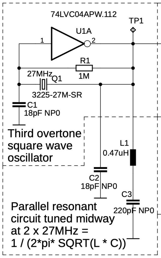
If you remove the inductor L1 and the capacitor C3, you get a standard oscillator. In this case it will oscillate at 27MHz. Notice also the value of C1 and C2, both being 18pF. Their value in standard oscillators is usually equal, and is selected depending and the quartz crystal used. In a very simplified way, their value is double of the crystal specified capacitance. (Our crystal datasheets says it is a 9pF crystal). For now, while ignoring the PCB traces capacitance, we must look at the C1 and C2 that they are connected in series (18pf in series with 18pF = 9pF), and together they are in parallel with the crystal. They are properly tuned to match the crystal which will in turn to mechanically oscillate with its factory tuned fundamental frequency of 27MHz.
Now add the L1 and C3. This will take the C2 side out of balance, in this case it will force the crystal to its 3rd overtone frequency.
Problems with the overtone frequency
When we built the above schematics in our lab, we experienced problems. Most of the time everything seemed right and the oscilloscope showed it oscillating at desired 81MHz. Sometimes, but only sometimes, after we powered up the circuit, it only oscillated at its fundamental frequency of 27MHz. As soon as we touched the circuit with a finger, it jumped up to its intended 81MHz and then it stayed there.
It was clear, that it is not reliably starting up. We figured, that we might need to find a different 27MHz crystal, and/or fine tune the values of the L1 and C3. That and more is described in several other blogs.