
Growing plants indoors is about light and water management. This article shares some thought on the later, specifically we show you schematics section how to connect the water pump and the flow sensor to common microprocessor..
TESLA Microgreens Stand is an automatic machine not unlike an Italian espresso machine or professional dishwasher. When looking from outside, all three might look like they have nothing in common. Inside is another matter, they all must precisely measure and distribute water.
From embedded design perspective they share electromechanical components, specifically the water pump and water flow sensors. Both of these components are manufactured in various sizes, designed to handle different water flow rate, in metric system defined by liter per minute [L/min]. There are of course many details to consider:
- Voltage AC or DC
- Flow rate [L/min]
- Submersible or not
- Noise level
- Water temperature handling
- Overall size
- Inlet type and diameter
- Outlet type and diameter
Regardless of any of the above parameters, your application either requires to regulate the pump rotation speed; or only needs to turn the pump on or off. If a fixed speed is acceptable, the pump can be turned on via standard (or solid state) relay. For our application we must control the pump rotational speed via the PWM (Pulse Width Modulation). This capability is available in almost every microprocessor.
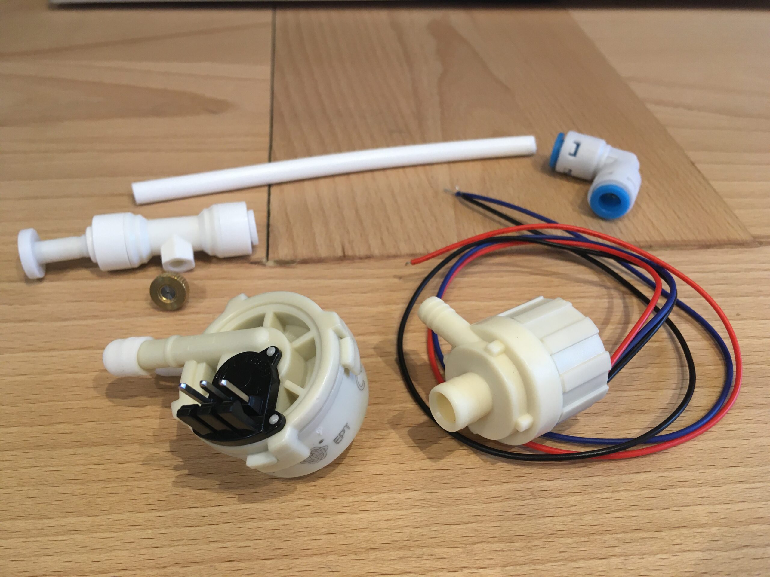
Small water pumps with three wires are often DC motors with the third wire being an input to control the speed, check manufacturer’s specification. In the picture above notice the pump has three wires; two for the pump 12VDC power and the third one for 5V PWM speed control. The same pump is available with two wires only, without the ability to change the speed (even though you can still hack it if you PWM control the power).
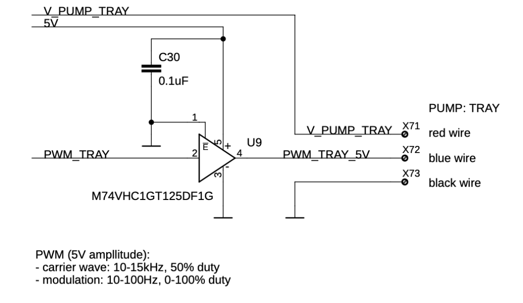
We are using STM32G0 series processor to independently control all eight pumps in our equipment. Our processor is 3.3V powered and we must use buffer driver to shift the voltage level to control the pump PWM pin:
To measure the actual amount of water flowing to all plants on every shelf, we attach a flow sensor in series with each pump. We recommend to mount each sensors on the inlet side of the pump, believing that the flow will avoid some pressure jumps which are stronger on the outlet side, but maybe it doesn’t matter.
Most inexpensive flow sensors have rotating propeller with magnets and sense the propeller rotation using a three pin Hall effect sensor device, outputting a 50% duty cycle square wave via its open collector output. Very often the Hall effect sensor requires 5V power.
One important thing to mention is that while most microprocessors are 3.3V powered, they have at least some 5V-tolerant inputs. Open collector output of the flow sensor would allow its output to be pulled to lower voltage of 3.3V and that would be all needed to do. We wanted that we are flow sensor type independent and prepared ourself for a 5V square signal. Did you know, that the 5V-tolerant inputs of many microprocessors DO NOT ALLOW to use its software controlled internal processor pull-up resistors for signals above 3.3V? That is why for our design we use external pull-up resistors:
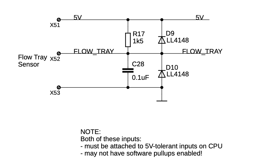
You must have the pull-up resistor, but could skip the capacitor and the two diodes. For the few cents they cost it is worth to consider they help to cleanup the signal and protect the input pin.
We have software interrupt on this input pin and count the arriving clicks. The sensor manufacturer states how many pulses to expect for various sensor types. For example our sensor specification is 90 pulses for (L/min) with an error +/- 5%. The software must measure the frequency of arriving pulses and the duration of the square wave, or simply to count the pulses and calculate the volume of water passing through.